A Distance Sensor Calibration Mechanism
by Chris Chapman
February 2002
These are some photographs of a distance sensor calibration
rig. It was designed to provide highly accurate horizontal movement
and stable vertical positioning of anything that you might want to fix
to it - such as the magnetic distance transducer for a seismometer shown
here.
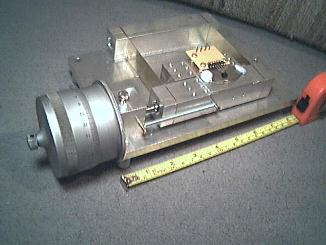
Image 029
General Layout
The mechanism is mounted on a 3/8" thick aluminum alloy baseplate,
8.25" long by 5.5" wide. There are three short legs which hold the
baseplate and the large micrometer drum clear of the table. The rectangular
bar at the rear is screwed on the baseplate on a 3mm spacer. Two
gold colored brass spring strips connect this to the moving rectangular
bar at the front and they are held in place by end plates with a single
bolt into the end of each bar. The wide spring strips prevent any
vertical movement of the moving bar. The moving bar has an array
of 3mm holes tapped in the top and is shown with a mounting plate and a
"butterfly" magnet (4 pole; i.e., 2 magnets together as a single cohesive
unit), held in place with two bits of blue mastic. The shorter mounting
bar immediately behind the front one is bolted to the baseplate on a 3mm
spacer and also has an array of 3mm tapped holes in the top. The
orange circuit board carries a small fixed black Hall sensor with three
leads and is mounted on three adjusting screws on top of this bar.
Too give a sense of scale, I have put a yellow tape measure with a red
drum/holder showing inches and centimeters (cm), in front of the rig.
It all seems to work very well.
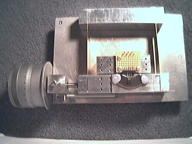
Image 032
Top View
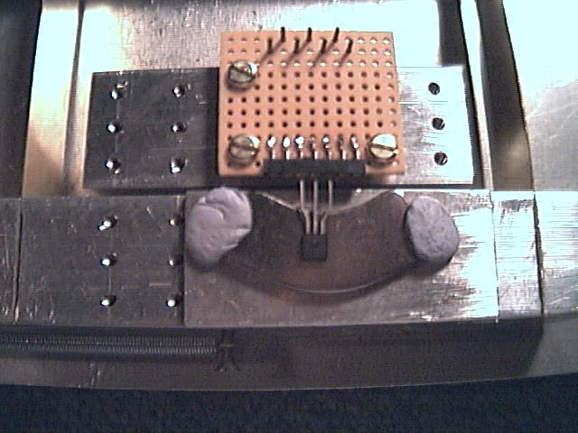
Image 034
Sensor Mounting
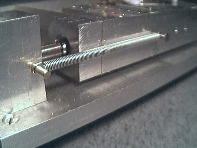
Image 037
Return Spring and Ball Drive
In the construction, I used HT15 Al alloy, brass strip and stainless
steel bolts as far as possible. The only bits which are magnetic
are the return spring, the centre bar of the micrometer drive and the ball
bearing.
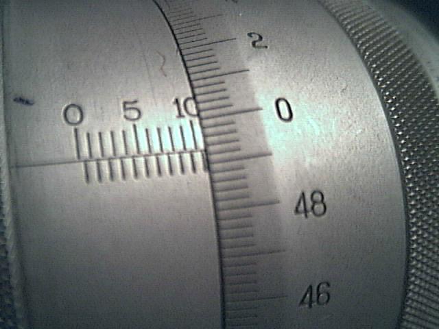
Image 038
Micrometer Drum
The Micrometer drive drum is on the left and has a travel of 25mm
and a resolution of 2 microns. The rotating center drive rod,
presses up against a ball bearing in the head of the end bolt of the moving
arm. The moving arm is kept in good contact with the micrometer centre
rod by the adjustable spring on the front face.
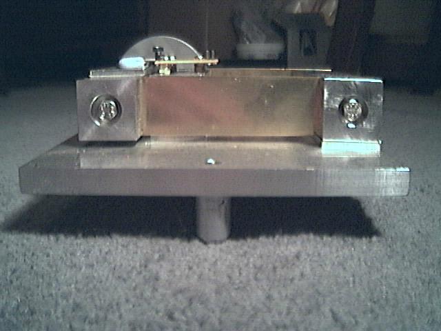
Image 040
End View
See some results of this instrument at:
https://seismograph.tripod.com/linearsensors.html
Chris Chapman