Linear Magnetic Sensors for Seismometers
By Chris Chapman
I have been doing some experiments using NeBFe (Neodymium) magnets and Hall effect linear sensors to make a fairly simple and inexpensive linear position sensor, suitable for use with with pendulum / feedback type seismometers.
The magnets are about 36 mm long, 20 mm wide and 2.5
mm thick. See the description / photo at http://www.wondermagnet.com/dev/magnet2.html.
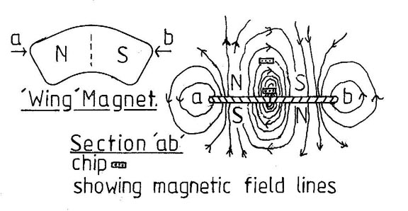
These "wing" magnets are "recovered" from failed computer hard drives.
The magnet is magnetized through the thickness with one "wing" having a
N pole and the other wing having a S pole on the same flat face.
The illustrated dotted line where the poles join in the middle of the face
gives an extremely sharp magnetic junction. The chip is shown in
the high sensitivity position close to the magnet and in an extended range
positon well above the magnet.
The Hall effect sensors have a Hall element, a current supply and a low noise amplifier all on the same chip. See http://www.allegromicro.com/sf/3515/index.htm. You can buy them in small flat plastic cases with three long legs (wires), similar to ZTX series transistors or in minature plastic cases as surface mount devices. See http://www.allegromicro.com/salesloc/sal2nam.htm for Allegro stockists/distributors.
The Hall sensors need a stable low noise 4.5 to 5.5 volt power supply and give almost rail to rail outputs which is ratiometric with the supply voltage. The linearity does fall off a bit within 0.5v of the supply rails, but this does not seem to be significant limitation in practice. The devices have three leads, the +ve and 0v supply rails and an output pin which is at about 1/2 the supply voltage for zero magnetic field input. The output does have a significant noise component and efficient filtering at a frequency of 10hz or below is required for seismic systems.
In use, the sensor package is mounted parallel to the
face of the magnet at it's centre line, allowing some vertical clearance
- I use 1/2 mm (0.020") as a minimum practical air spacing. This
gives a sensor chip to magnet face separation of approximately 1.0 mm.
You may move the chip and hold the magnet still or vice versa. As
the relative positions of the chip and magnet change, the output voltage
of the chip follows the perpendicular component of the magnetic field at
that point. This gives a quite remarkably good high sensitivity straight
line calibration in practice - see the graph below. The sensitivity
and range may be controlled by altering the clearance between the sensor
and the magnet face - the larger the air gap, the lower the sensitivity
but the greater the linear range. These chips have a maximum magnetic
field that they can detect before the ouput reaches the supply rails.

The plot shown above is of the output voltage versus the position of a simple sensor system. The sensitivity was measured at 5.8 mV / micron and the total linear range was 0.8 mm.
The signal may conveniently be amplified, filtered and referenced to zero volts and a "DC" output pin provided. The signal is then passed through a high pass filter to eliminate any slow drifts and a second amplifier / filter system to scale the output to match an A/D converter. The outputs may be used to drive the feedback amplifier of a SG (Shackeford/Gunderson) type broad band seismograph. The "DC" output may be used for a three component "wide band" feedback system.
The minimum movement which can be measured (the resolution) depends on the sensitivity and on the noise level present on the output signal. With a three pole 10 Hz Butterworth filter, I measured the noise level at less than +/- 100 micro volts peak to peak, over a 100 second period. With a sensitivity of 5.8 mV / micron, this corresponds to a bit under +/- 20 nano metres and the linear range is 0.8 mm. If you increase the sensitivity to 10 mV / micro, you get down to about +/- 10 nano metres resolution, but you have only ~ 0.5 mm total linear range. This is OK in a feedback instrument, where the feedback system holds the pendulum nearly still, but a moderately energentic local quake could drive a simple pendulum system out of range. It also requires considerable care to set it up to mid range.
If you mount the large size bipolar "U" or "I" unshielded magnet of a "traditional" magnet / coil detection system on a pendulum, it can experience forces due to changes in the local magnetic field and move the pendulum in response. You are likely to see both noise and interfering signals. These local magnetic field changes may be due to changes in the Earth's field itself or due to the influence of passing trains, lorries, cars, household electrical appliances, etc. This sensitivity is greatly reduced with the "four pole" magnets, since the poles are close together and occur in pairs. While one pole might experience a small push due to the external field, the adjoining pole a few mm away will experience a similar pull and these forces very nearly cancel out.
The stray magnetic field may be almost completely screened using a "U" channel made from mild steel sheet. This screen may also be used to control the overall sensitivity of the sensor, by setting the spacing between the magnet and the screen "counterface". Mounting a screened sensor magnet on the pendulum has the advantage that the pendulum does not have to be fitted with wiring for a Hall chip. This helps to reduce RF (Radio Frequency) and electromagnetic noise pickup.
The strength of the magnets, the sensitivity of the Hall devices and their precise position in the magnetic field will all effect the output calibration. You can get a reasonably accurate calibration of your system by sticking a 3 mm diameter ball bearing on one side of the pendulum and fitting a screw stop to the frame to make contact with it. Connect a DVM (Digital Volt Meter) between the ouput pin of the chip and 0V.
Use the leveling screws to tilt the seismometer so that the bearing rests up against the stop, adjust the stop to the lower end of the voltage measurement range, read the voltmeter, insert a suitable feeler gauge between the bearing and the stop and then read the voltmeter again. Dividing the change in the voltage output by teh thickness of the feeler gauge will the sensitivity to ~ 5%.
I wish to acknowledge that these experiments were based
on the extensive pioneering work done by Meredith and Robert Lamb.
I thank them very sincerely for all their advice and help. See:
http://www.geocities.com/meredithlamb/index.html
Reference to the Distance Sensor Calibration Mechanism
used for this study:
https://seismograph.tripod.com/distancecalibrator.html
Chris Chapman